By John Siau
April 17, 2014
In my last post, "Audio that Goes to 11", I made the bold assertion that most of our audio recordings contain peaks that exceed the limits of our digital hardware. In this post I will show how this happens, and explain why this is a problem in PCM audio systems. In a must-see short video clip from "This is Spinal Tap", heavy-metal guitar player Nigel Tufnel eloquently explains that his Marshal amps "go to 11 ... one higher than 10".
The 16-bit digital system used on CD recordings can quantize audio into one of 65,536 levels (-32,768 to +32,767). But, to keep things simple, we will adopt Nigel's "0" to "10" scale. In a 16-bit system "10" is really 32,767, and "-10" is really -32,768. Here is how it looks:
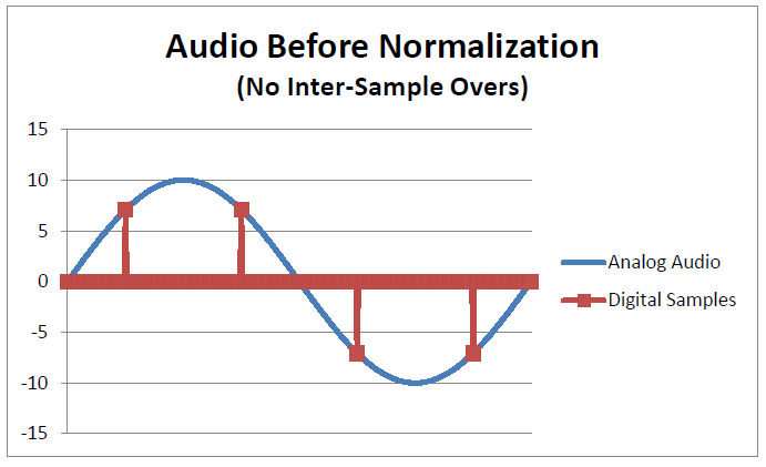
We have sampled an analog audio signal (blue trace). The digital samples are shown in red. Samples are an instantaneous snapshot of a continuous waveform. Our "snapshots" show two samples at about +7 followed by two samples at -7. Note that the input audio is just reaching "10", but the samples only reach "7". Our digital sampling system has missed the peaks and is erroneously showing a peak value of 7 instead of 10.
The amazing thing is that the analog peaks at +10 and -10 are not really lost. We can reconstruct an exact replica of the original analog sine wave, at exactly the correct amplitude using the interpolation and reconstruction filters that are normally incorporated into a DAC. Interpolation recovers the missing information between samples. Interpolation looks like this:

Life would be good if we never exceeded "7" on Nigel's scale. Nothing would ever clip because we would be allowing ample headroom in our digital system. In practice, this NEVER happens.
Nearly all commercial recordings use a process know as "normalization" to boost the audio to maximize the use of the dynamic range of our digital systems. Typically, each digital track is scanned to find the highest sample code in the track. Once this highest code is found, the entire track is turned up until the highest sample just reaches the maximum code. CD's are normalized so that peak codes just reach +32,767 or -32,768. The following chart shows this using a simplified -10 to +10 scale:
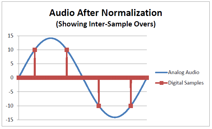
We now have digital samples reaching "10" and "-10". Our samples don't exceed "10", so we have not clipped our digital storage system. We have maximized the loudness of our recording and are now maximizing the use of our digital storage system. Life is good - almost.
The problem occurs when we try to play this normalized audio. The DAC will apply interpolation to reconstruct the original waveform. This time, we encounter a problem. The interpolator clips at "10". Here is the result:
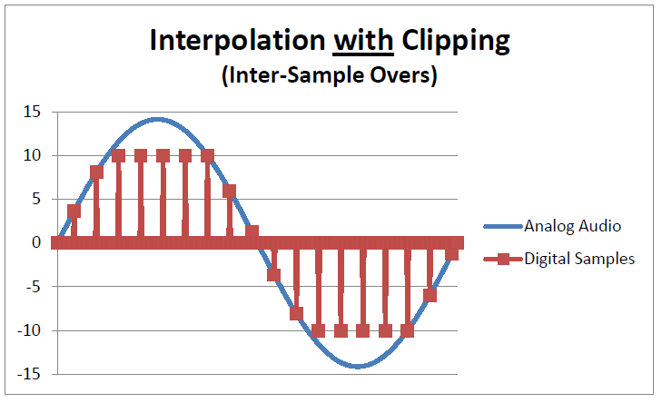
The interpolation filter has clipped the waveform and is now generating high levels of distortion. Our digital system has failed to deliver the "perfect sound" that was claimed when the CD was introduced. Does this mean that PCM audio is broken? Should we move to DSD to eliminate interpolation filters? What is the answer?
The answer is headroom. All signal processing steps in the audio chain need headroom. We need headroom in the analog sections, and we need headroom in the digital signal processing.
If we add the required headroom to the interpolation filter we get the following results:

With adequate headroom, the DAC accurately reproduces audio "going to 14". The inter-sample overs are not clipped and distortion is avoided.
Our DACs go to 14
If we are going to use Nigel's scale, I guess you could say "our DACs go to 14"! The Benchmark DAC2 and DAC3 series converters have 3.5 dB of headroom above 0 dBFS.
It is my opinion that the clipping of inter-sample overs is a major issue. The solution is not to eliminate interpolation filters. The solution is headroom. Benchmark added this additional headroom starting with the DAC2 series converters.
Additional Reading:
"Overload in Signal Conversion", Nielsen and Lund, TC Electronics (PDF)
"Over The Top - Measured Results", Jim Lesurf, AudioMisc
"Avoiding Inter Sample Peaks", des, Hometracked.com


